Preparation time: Around 4 hours with a moderate iron. Serves 1 with thick, buttery bass.
Ingredients:
1 x Pedalboard reclaimed from a 1970's Hammond organ. Clean well.
1 x Arduino Nano
1 x YwRobot 2x16 I2C LCD
6 x Arcade buttons with integrated LEDs
1 x 5 pin din MIDI socket
19 x 1N4148 diodes
1 x 220 ohm resistor (for MIDI out)
1 x Aluminium treadplate (2mm) and rivets, chopped and folded
1 x Self adhesive vinyl decal
Garnish with Hookup wire
Season well with Nuts, bolts, screws
I had wanted to get hold of a set of MIDI bass pedals for a very long time, in part ever since seeing people such as
Pete Trawavas with Marillion, Geddy Lee with Rush playing Moog Taurus pedals. However, I wasn't going to rush out and spend hundreds of pounds on
something that is a pretty basic requirement. I'd also not had any donor pedal switches to work from - until my friend Chris McMahon randomly offered
me a set of pedals that had cluttered up his cellar for the last 10 years! I would again use an Arduino (nano in this case) and also have some features
such as an LCD screen, and buttons for MIDI program up/down, octave up/down and hold/mono/poly modes as they seemed important to me.
The pedals were from a 70's Hammond organ, and even still had a (faulty) volume pedal, and the power amp for the organ. The pedals themselves
were somewhat rusty, but generally looked to be in working order with 13 pedals. I managed to salvage the pedals, and ended up keeping part of the
plywood base as the mounting was already the right height off the floor.
One thing I noticed straight away which was interesting were the dual contacts, ie a contact for the rest and the 'on' position.
I knew from previous keyboard designs that it would also then be possible in theory to create velocity sensitivity through measuring the time
between the rest and 'on' positions (faster = it was hit harder). Of course in the Hammond this was not velocity sensitive, the wiring indicated
that it was used to connect the keys from top to bottom in a row such that the bottom-most key would sound (and the ones above disconnected by the
'rest' contact of the sounding key) as a sort of analogue key priority system.
After making the MIDI melodeon, i'd had some practice of key scanning with diode matrices, so I decided to reuse the principles on the bass pedals.
However, I also considered that the layout of the key switches was important, as I would somehow need to simultaneously read the 'rest' and 'on'
contacts of each key at the same time, otherwise the timing calculation would be inaccurate due to the time it takes the Arduino to move to the next
'row' of contacts to read the 'column' of switches. After some consideration I dedided to use the PORTs on the Arduino to read 8 bits simultaneously
(as it worked out only using 6 of these bits as PIND lowest 2 bits are the USB pins which I would bitmask out) and 6 'row' outputs (which would
support the 26 key contacts I needed for the pedals - being 13 pedals x 2 contacts). Seperately I also had 1 row to read the 6 'function' buttons
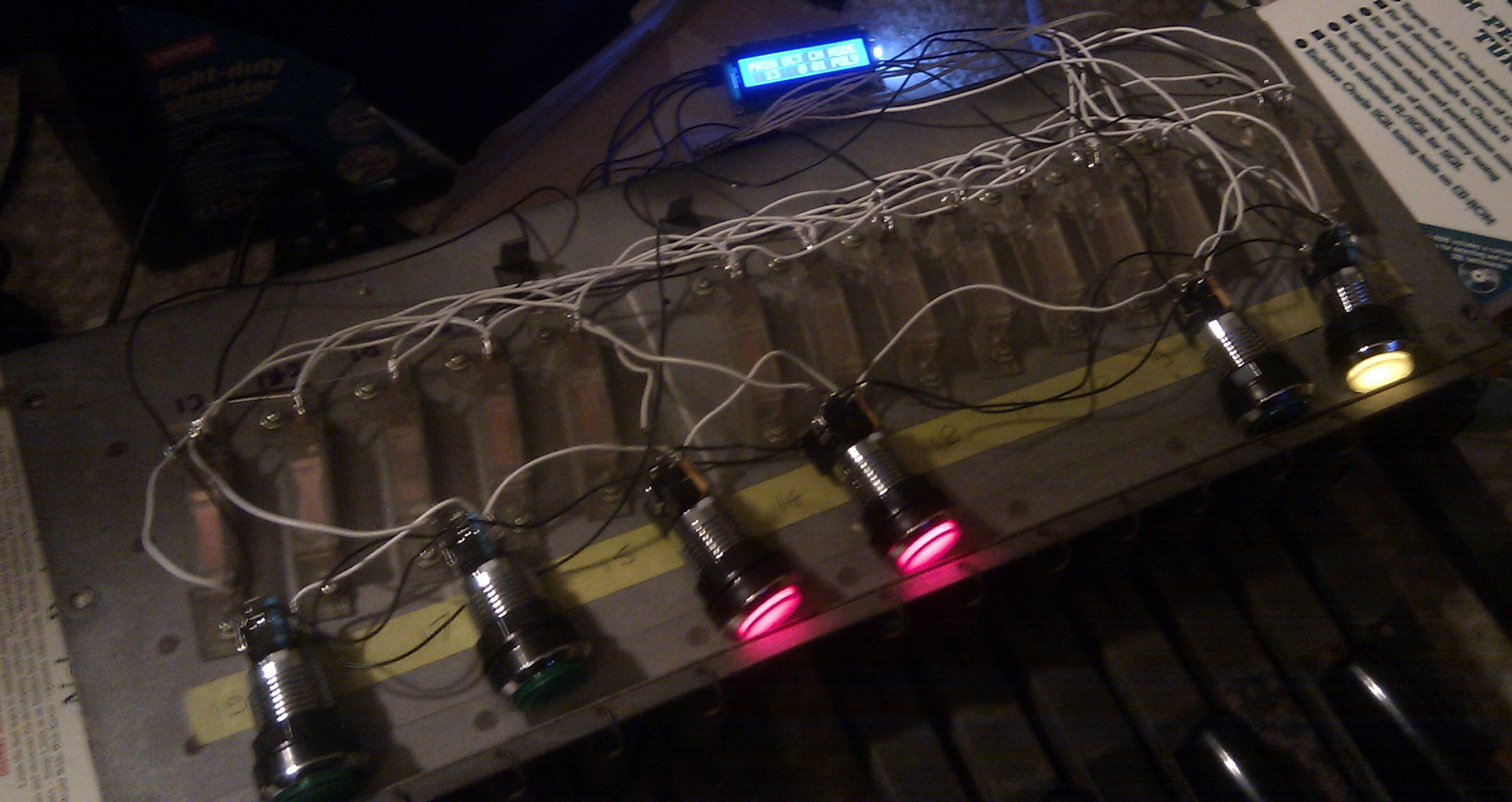
simulaneously. In the picture here I had just wired up two pedals (4 contacts) and got the LCD working (a 2 wire I2C display). The debug was showing the
contact positions in the rest position. All was looking good.
I had also worked out that rather than every contact requiring a diode, I could take advantage of the switch pole mechanics whereby it couldn't
simultaneously touch the 'rest' and 'on' contacts (which you would normally need to decode if each of the 26 [2 contacts x 13 pedals] were
genuinely independent switches) - this saved a lot of diodes as there was just one per pedal and per function button. From that point, it was just
soldering and wiring up the rest of the system. One feature that I also decided to use was to connect some of the LEDs in the buttons (which are
arcade machine buttons) to 3 PWM outputs I had available (GREEN for octave up/down and BLUE for mode), such that they would look cool glowing in and out. I also came
up with the concept that the octave up/down buttons would glow with a speed that indicated how many octaves up/down you were (glows per second =
number of octaves)!
The connections to the Arduino were as follows:
Port B (pins D8-13) - all outputs, used for MIDI out, 3 x PWM out and key scan out 0,1
Port C (pins A0..5) - all outputs, used for key scan out 2,3,4,5, LCD SCL and SDA
Port D (pins D2-7) - all inputs except USB TX, used for key scanning inputs on bits 7..2 (bit 1 = USB TX, 0 = USB RX)
Pin D2 - key scanning input 0 (internal pull-up enabled) - C1,D#1,F#1,A1,C2 bottom contact direct, Oct Down via diode
Pin D3 - key scanning input 1 (internal pull-up enabled) - C1,D#1,F#1,A1,C2 top contact direct, Oct Up via diode
Pin D4 - key scanning input 2 (internal pull-up enabled) - C#1,E1,G1,A#1 bottom contact direct, Prog Down via diode
Pin D5 - key scanning input 3 (internal pull-up enabled) - C#1,E1,G1,A#1 top contact direct, Prog Up via diode
Pin D7 - key scanning input 5 (internal pull-up enabled) - D1,F1,G#1,B1 top contact direct, Function via diode
Pin D8 - MIDI output (controlled through NewSoftSerial library)
Pin D9 - PWM output to Octave Down LED
Pin D10 - PWM output to Octave Up LED
Pin D11 - PWM output to Mode LED
Pin D12 - key scanning output 0 - C1, C#1, D1 pole via individual diodes
Pin D13 - key scanning output 1 - D#1, E1, F1 pole via individual diodes
Pin A0 - key scanning output 2 - F#1, G1, G#1 pole via individual diodes
Pin A1 - key scanning output 3 - A1, A#1, B1 pole via individual diodes
Pin A2 - key scanning output 4 - C2 pole via diode
Pin A3 - key scanning output 5 - Function buttons common
Pin A4 - LCD SDA output
Pin A5 - LCD SCL output
Pin 20 - MIDI in (unused, but needed to assign this somewhere for NewSoftSerial)
This meant that every usable pin was in use (keeping USB for debugging), some choices were fairly fixed (eg the SCL/SDA pins and PWM)
The diodes were required to ensure that there would be no 'ghost' buttons detected if several pedals or buttons were pushed simultaneously. The diodes are connected with the cathodes towards the outputs of the Arduino such that if a key is closed, then the normally pulled-up voltage (via the internal pull-ups on the Arduino inputs) are grounded by the output pin going low.
Here is the way the pedals/buttons are mapped across the key scanning rows and columns. Columns are read in one go via a PORT read which reads 3 pedals together or all function buttons.
Row/Col
Col in D2
Col in D3
Col in D4
Col in D5
Col in D6
Col in D7
Row D12 out
C1 bottom
C1 top
C#1 bottom
C#1 top
D1 bottom
D1 top
Row D13 out
D#1 bottom
D#1 top
E1 bottom
E1 top
F1 bottom
F1 top
Row A0 out
F#1 bottom
F#1 top
G1 bottom
G1 top
G#1 bottom
G#1 top
Row A1 out
A1 bottom
A1 top
A#1 bottom
A#1 top
B1 bottom
B1 top
Row A2 out
C2 bottom
C2 top
(unused)
(unused)
(unused)
(unused)
Row A3 out
Octave Down
Octave Up
Program Down
Program Up
Mode
Function
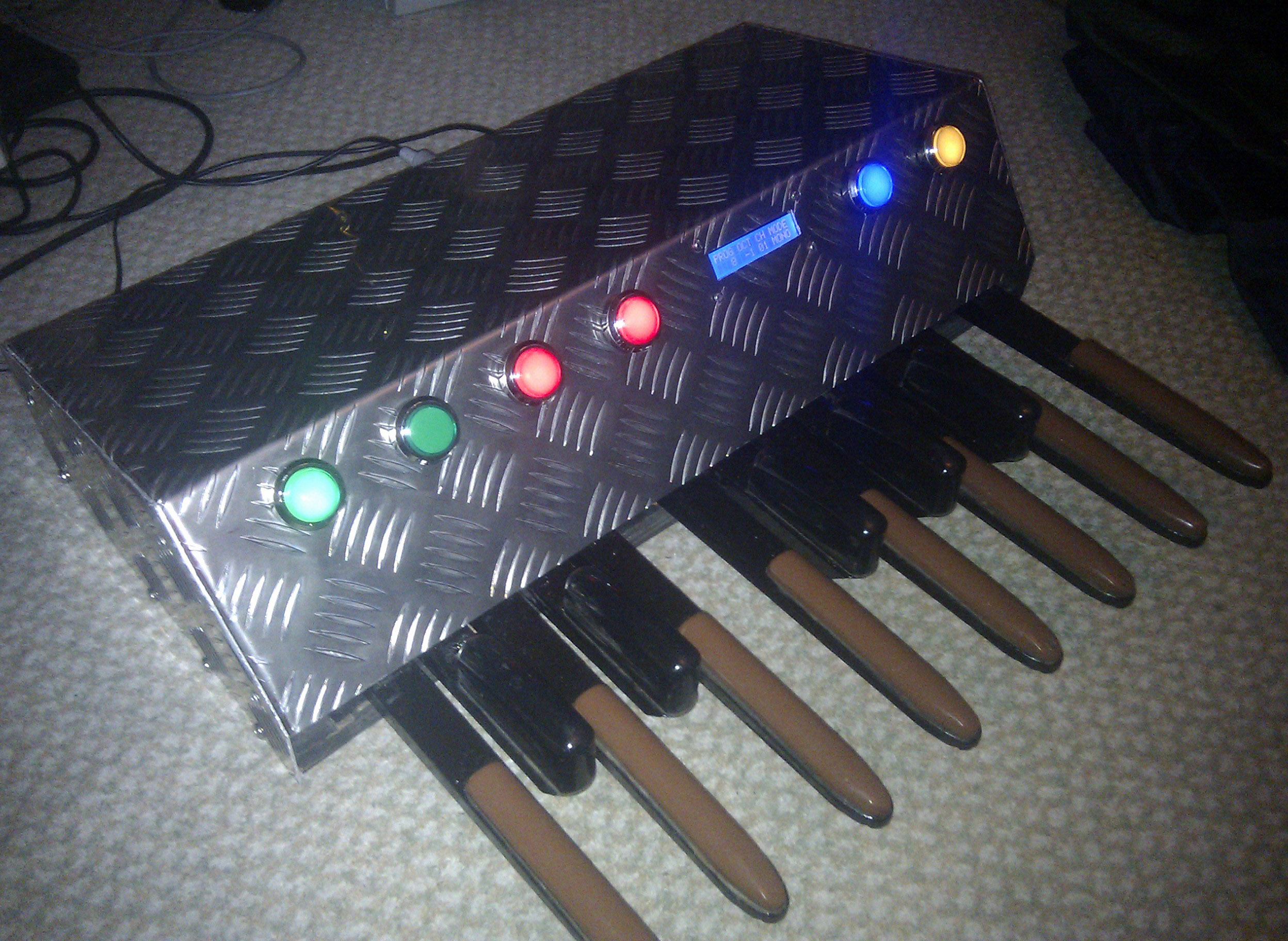
The MIDI program change buttons RED (just up and down) and the 'function' button YELLOW (which doesn't do anything yet) would have the LEDs permanently on as
you can see in this picture. Incidentally, I hadn't realised upon ordering that the arcade buttons had resistors in for the LEDs valued for power
from 12V. I did try altering the values to run at 5V (which is what the Arduino supplies), but they were plenty bright enough with the original
resistors in place.
Here you can see the detail on the LCD. I used a 'YwRobot' 2 row x 16 character blue one, see info here.
It was really easy to use, once you have included the LCD library, it basically allows printing to screen positions. I decided to display all
the main status information, ie MIDI program number, Octave, MIDI channel and the mode (MONO which also holds the last played note, and POLYphonic).
The LCD is also very handy in that you only occupy two output pins on the Arduino, most other LCDs take up a lot of your output pins.
I next turned my attention to building a case for the pedals. I wanted them to look 'rocky' and after dismissing building a wooden case I thought
that aluminium treadplate would both be lightweight, strong and industrial looking. In order to work on the case design, I built a mock-up out of
some spare cardboard so that I could check the internal clearances, and measure up the size of treadplate required. The arcade buttons are also
quite deep, so I could play around with the mounting positions and check that it would all fit.
Close-up inside the mocked-up case. You can also see here the key contacts top and bottom, and one of the diodes connected to the switch pole
in the centre.
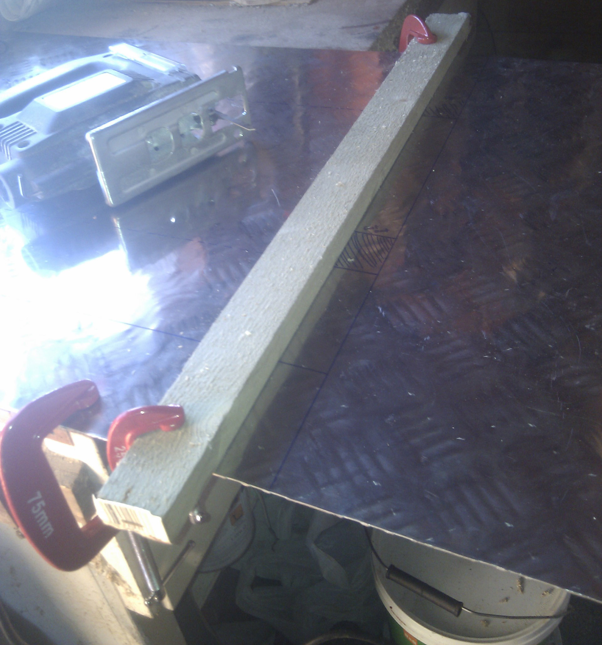
The case would also need some ends, and I'd have to attach these to the main sections. I worked out that a fairly straightforward way was to
fold the ends over a little, and then rivet on flat end plates. You can see the detail here around the folds.
And here with the mocked-up end plates attached.
So then it was time to make the case for real, here it's marked out.
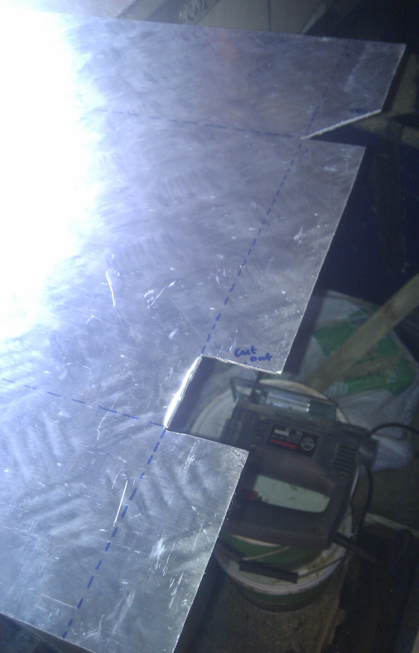
And here just about to cut the sheet down to size initially which I did with my jigsaw.
And then to cut out some notches which would be required to prevent overlap when the main sections were folded over.
And here is following the folds. There were 4 folds required - one on each end to form the 'flaps' where the end plates would be attached,
and a fold at the front and the rear of the main sections. I didn't have access to a bending jig, but after some research I found a really
friendly machine shop not far from home, and they made very light work of bending it on their huge press for a few pounds fee. Extremely straight
bends! You can also clearly see how the notches I had cut into the metal worked out well.
Here are the marked up end plates ready for cutting, which I did again with the jigsaw.
And here are the end plates test fitted, prior to riveting.
Next I turned my attention to mounting the various parts onto the case. One problematic part was to mount the Arduino nano. I had decided that a
really easy way to power the device would be to use a spare mini-USB 5V mobile phone charger (from an old HTC handset) and so the USB port would
need to be externally accessible. The mounting holes of the Arduino PCB looked really fragile, and would probably break quickly. I found a spare
strain relief metal clamp (from an old D25 RS232 plug) and sawed off part of it with the screw thread. This was bent and soldered to the top of the
mini-USB socket, so that this could be screwed to the case. It worked out really well and strong.
Here you can see part way through the mounting of the LCD. I used some bolts (which were trimmed to length) with double nuts to position the LCD without bending the PCB. On the
front of the LCD I cut up part of an old cassette box (lacking anything better) to provide some transparent but tough cover to protect the LCD front.
You can also see one of the arcade buttons, they have easy to use plastic nuts on the inside, and the microswitches/LED assemblies just twist off.
Here's the other side of the Arduino, and also the MIDI output socket mounted.
The detail of the buttons mounted. From left to right they are: Octave Down, Octave Up, Program Down, Program Up, Mode, Function.
And here with the LCD test mounted.
I then started doing a mini refurbishment of the pedal mechanism. In order to centre the rear of the pedals, there are felt bushes and metal flanges
both of which were worn / opened up too much. Some fettling (which mainly consisted of bending the flanges in, and turning the bushes around to
use previously unworn ends) managed to improve this satisfactorily.
There was also some obvious signs of age where the paint has worn away, and the metalwork was becoming rusty.
After cleaning off the loose paint and rust, a coat of Hammerite black paint helped sharpen this up.
Here you can see the pedals just prior to finishing with the end plates riveted on, and everything fitted. All that remained was to drill the holes
and fit the wood screws to attach the aluminium case to the wood base plate and 'risers' that the pedal mechanism sits on.
The finishing touch was to order a decal from an internet shop to set off the design. I chose the name 'WOMinator' partly as a homage to old 80s
keyboards such as the 'EMUlator' and also WOM invoking memories of the big fat Moog Taurus type sounds that I planned to play with this. I did find a
sample library of Moog Taurus bass sounds which I made into a sample bank for my SD card MIDI sample player. It works great!
And again here's the front view of the finished product.
The code is fairly simple really. Here's a few highlights though:
The Wire and LiquidCrystal libraries are used for I2C (LCD physical interface) and LCD routines for printing / cursor location etc
The NewSoftSerial library is used to create a software UART at 31250 baud for the MIDI out. This is because otherwise you have to use TX/RX which kills the USB port (used for my debugging)
The ports are setup for I/O as per the description earlier on. We enable the internal pull-ups on inputs by writing HIGH to the input pins
Three arrays are used to track what's happening - keyActive (means pedal is 'on' this time around the loop), LastkeyActive (pedal has been processed as 'on' in a previous loop iteration) and keyTimer which counts the time between a pedal being 'off' and it reaching the 'on' position
The main program loop scans keys, sends any MIDI (note on, off, program change), reads the function buttons, updates the PWM LED brightness (if any are on) and updates the LCD if any of the relevant display items have changed. There is also a 1ms delay in the loop otherwise I found that the velocity reading was difficult to get working.
The scanKeys function looks at groups of inputs for the pedals. It uses bitmasks to pull out the contact pairs, and then looks at whether it's transitioned from 'off' to 'in between' (if so it starts counting down keyTimer from 127), or if it's fully 'on' of 'off'. There are different lines to cope with the fact that not all positions in the diode matrix have pedals connected
outputMIDI has some switches to cope with the play mode - either polyphonic which is 'normal' or MONO mode which only sustains the last note, and only sends a note off if the playing note changes to a new one. This also calculates the velocity for note ons from the value of keyTimer such that fast transitions will result in higher velocities
doPWM deals with the fading in and out - which changes direction so it's a nice glow, and also the speed is variable for the Octave display to indicate how many octaves up/down - 1 fade per second per octave